Equation 1 will break down at those frequencies where rp1(f) is zero (or very close to it).
Measuring an organism's behavioral transfer function with a single square step transition from a variable interval (VI) schedule to extinction will have problems with spike artifacts. The spike artifacts are caused by zero, or near zero, amplitudes in the reinforcement schedule spectrum at frequencies important to the measurement. This note shows how the addition of a second burst of variable interval reinforcement with a different duration can fill in these zeros or holes.
Key words: linear systems analysis, frequency domain, variable interval schedules, step transition, transfer function.
While measuring the transfer function of pigeons, it became
apparent that zeros in the amplitude of the reinforcement schedule spectrum
could introduce spike artifacts
(Palya, Walter, Kessel & Lucke, 1996). The artifacts
are generated when computing a transfer function by the division of two FFTs
using the expression
![]()
Equation 1 will break down at those frequencies where
rp1(f) is zero (or very close to it).
Using a single square step transition from a variable interval (VI) schedule to
extinction (Palya et al., 1996) guarantees a set
of equally spaced frequencies where rp1(f) is zero.
Ignoring the local variations introduced by the variable interval schedule,
the reinforcement schedule is given by
The Fourier transform of Equation 2 is
Note that for non-zero frequencies, the factor
sin(2  fTVI/2) will cause
r(f;TVI) to be zero if fTVI is an
integer. If TVI = 200 sec, fTVI is
exactly an integer at f = +/- 5mHz, +/- 10mHz, +/- 15mHz,...
and so forth. These frequencies are exactly commensurate with some of the
frequencies returned by an FFT routine if Ttrial = 1000 sec.
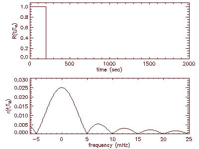
The amplitude (second factor) at low-frequency of Equation 3 with its
comb-like structure of zeros is shown in
Figure 1.
fTVI/2) will cause
r(f;TVI) to be zero if fTVI is an
integer. If TVI = 200 sec, fTVI is
exactly an integer at f = +/- 5mHz, +/- 10mHz, +/- 15mHz,...
and so forth. These frequencies are exactly commensurate with some of the
frequencies returned by an FFT routine if Ttrial = 1000 sec.
The amplitude (second factor) at low-frequency of Equation 3 with its
comb-like structure of zeros is shown in
Figure 1.
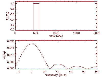
Figure 1 Top panel: Average reinforcement
rate for a single step transition from VI to extinction with
TVI = 200 sec and Ttrial = 2000 sec.
Bottom Panel: The low-frequency amplitude for Equation 3 with
TVI = 200 sec as computed with an FFT routine. Note that to
increase the resolution Ttrial = 2000 sec.
Adding a delay to the onset of the variable interval schedule burst will only
change the phase factor in Equation 3. If the delay is
![]() T , then the reinforcement
schedule, again ignoring the local variations introduced by the variable
interval schedule, is given by
T , then the reinforcement
schedule, again ignoring the local variations introduced by the variable
interval schedule, is given by
![]()
The Fourier transform of Equation 4 is
While the only difference between Equations 3 and 5 is the phase factor (first
factor in either expression), the frequencies with zero amplitude can always be
moved by changing the length of the delayed burst (i.e. changing
TVI). Figure 2 shows
the amplitude of Equation 5 in low-frequency region with
TVI = 141 sec and
![]() T = 431 sec.
T = 431 sec.
Figure 2 Top panel: Average
reinforcement rate for a single step transition from VI to extinction with
TVI = 141 sec,
![]() T = 431 sec,
and Ttrial = 2000 sec. Bottom Panel: The low-frequency
amplitude for Equation 5 with TVI = 141 sec and
T = 431 sec,
and Ttrial = 2000 sec. Bottom Panel: The low-frequency
amplitude for Equation 5 with TVI = 141 sec and
![]() T = 431 sec
as computed with an FFT routine.
T = 431 sec
as computed with an FFT routine.
If the two variable interval schedule bursts are combined, then the zeros left
by the first burst will be filled in by the second burst and vice versa. Since
the Fourier transform is a linear operator, the transform of the combined burst
is just the sum individual transforms,
Figure 3 shows the amplitude of Equation 6
in the low-frequency region. There are additional variations in the combined
amplitude from the phase factor.
Figure 3 Top panel: Average
reinforcement rate for a two bursts of VI surrounded by extinction with
TVI1 = 200 sec, TVI2 = 141 sec,
![]() T = 431 sec,
and Ttrial = 2000 sec. Bottom Panel: The low-frequency
amplitude for Equation 6 as computed with an FFT routine.
T = 431 sec,
and Ttrial = 2000 sec. Bottom Panel: The low-frequency
amplitude for Equation 6 as computed with an FFT routine.
One possible catch to this method of fixing the holes is a tacit assumption that the birds are 'linear' enough so the two VI bursts won't interfere. This can be tested by changing the duration, delay and VI requirement and seeing how much the obtained transfer function changes. If the birds are completely linear, a doubtful outcome, then the transfer function should be invariant. If the birds aren't completely linear, then the differences will set the scale of the non-linearity. However, unless the birds are wildly non-linear in their steady-state behavior, this method will improve the measurement of the transfer function.
Palya, W.L., Walter, D., Kessel, R., and Lucke, R. (1995). Investigating Dynamic Behavior with a Fixed-Time Extinction Schedule and Linear Analysis. The Journal of the Experimental Analysis of Behavior, 66, 391--409.